Bifacial PV module technology has seen a steep increase in interest from the industry on
the back of similar success of PERC technology enabled PV modules. The technology
however has been around for some time, with commercial production in place for over a
decade. So how are the conditions different now from a few years ago? What is driving
this widespread adoption of bifacial PV modules in the present time?
Several factors have made adoption of bifacial modules conducive from a technical and
commercial standpoint. The technical and commercial success of PERC models, the drop in
module prices, higher efficiency, decrease in the BOS cost such as trackers, etc. have
made adoption of the technology lucrative. An added benefit is the work put in by the
federal and private participants such as NREL, PVsyst and other component manufacturers
to improve the accurately of computed system yield, module durability and optimum
performance in general.
Peak yield from a bifacial system requires the optimization of several factors and to
varying degree of influence. These include albedo, ground coverage ratio (GCR),
elevation etc. The industry has also realized that coupling bifacial modules with
trackers returns a higher generation than bifacial modules on a fixed tilt system,
thereby lowering the Levelized Cost of Energy (LCOE) and improving the project Internal
Rate of Return (IRR). Some estimates claim bifacial gain as high a 30% with the right
conditions. As the technology matures and prediction techniques improve, more accurate
estimates of the gain offered by bifacial modules will be possible.
A Bloomberg report for H1 2018 puts the market share of bifacial modules at 3%, which is
expected to grow to 40% by 2025 as shown in Figure 2
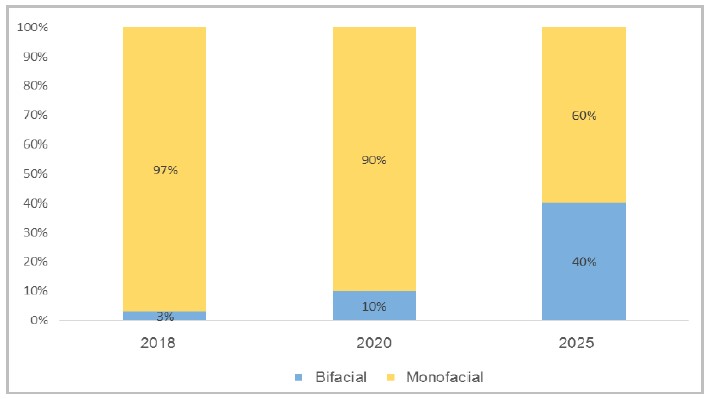
Figure 2: Bifacial module market share
With module prices continually falling, bifacial PV modules are expected to replace
monofacial modules, the current workhorse of the industry.
The paper starts with the basics of bifacial modules and covers the factors that need to
be addressed if such a system has to be optimized, as a one size fits all approach is
not possible.
WHAT ARE BIFACIAL PV MODULES?
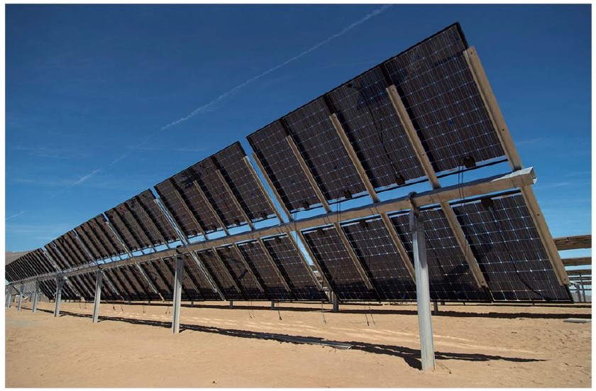
As the name suggests, bifacial PV modules can generate energy from the front and rear
side of a PV module. Unlike mono-facial modules, the rear side of bifacial modules is
lined with cells to capture reflected and diffused irradiation. A comparison of the two
is shown in Figure 3. The nameplate power of the rear side of the modules is however
less than the front side. Bifaciality factor quantifies the STC-rated power of a
bifacial module’s rear side in relation to the front-side power. These ratios range
between 55% and 95%.
-and-monofacial-PV-modules-(right).jpg)
Figure 3: Bifacial PV modules (left) and monofacial PV modules
(right)2
Bifacial technology is essentially a derivative of Passivate Emitter and Rear Cell (PERC)
technology, as the name suggests, both having a rear passivation layer that improves the
ability to trap light. The difference being replacing the fully metalized rear electrode
(aluminium layer) in PERC with selective metallized contacts that allow light to pass as
shown in Figure 4.
-and-bifacial-cell-(right).jpg)
Figure 4: PERC cell (left) and bifacial cell (right)3
HOW BIFACIAL MODULES ARE DESIGNED
To boost energy generated from the module, every part of the module is designed to
maximize light absorption and consequently higher energy gain. The Gain of a bifacial
unit is defined as;
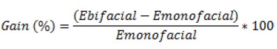
Several factors influence the overall gain. These include:
- Cell technology
- Module design
- Installation choice
- Ground conditions
- Surface reflectivity
Choice of cell technology relates to selection of n/p-type and mono/poly PERC.
Installation choices relates to fixed/tracking system, tilt, pitch etc. Ground
conditions relate to irradiance, latitude, longitude etc. Surface reflectivity is known
as albedo. While module design is discussed in this section, installation choices and
surface reflectivity will be debated in the following section.
Area between the cells is designed to either allow passage of light to the rear side or a
layer called ceramic glass which is essentially a reflective layer is added under the
cell layer as shown in Figure 5. Manufacturers claim using ceramic glass increases the
nameplate rating by 5W.
-and-ceramic-glass-(right).jpg)
Figure 5: Fully transparent rear glass (left) and ceramic glass
(right)4
To achieve light transmission, early variants of bifacial modules that appeared in the
market were frameless and dual glass. Manufacturers claimed these designs afforded the
module low moisture transmission rates and made the module less susceptible to PID among
other benefits. Currently available bifacial modules are available as dual glass or with
clear backsheet. In sandy environments, double glass models provide an additional
barrier. Using transparent backsheet is beneficial when lightweight models are required.
However, transparent backsheets are challenged by UV radiation and hence testing to
ascertain their weakness is crucial.
According to DuPont, testing polymer-based backsheets with controlled humidity is the
prime test in combination with thermal cycle for determining embrittlement effects.
The choice of using framed or frameless models depends on the application. For tracking
and floating solar plants, framed models are better suited for their higher stability
and resistance against mechanical stress. Due to the nature of the design requirement,
rear-side busbars is necessary and cell stringing mirrors that of the front side.
Frameless modules are also less prone to PID.
A key requirement for optimal performance of bifacial modules is to minimize shading on
the rear side. Junction boxes are hence become smaller and in some cases separated into
multiple units placed along the panel’s edge. All of this results in better thermal
management and hence bifacial modules usually have a better temperature coefficient than
conventional monofacial modules.
The robustness of bifacial module design in general is reflected by the lower annual
degradation rate. The current industry average is 0.5%/year.
PLANT DESIGN AND FACTORS TO BE CONSIDERED
Energy generation and Performance Ratio (PR) depend on several factors. While the choice
of cell technology and PV module design form the foundation for an optimum system, plant
layout and associated ground conditions can facilitate or hinder these objectives.
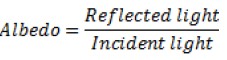
To optimally operate a bifacial PV plant it is essential to ensure adequate reflected
light is incident on the rear side of the module. This is essentially dictated by the
albedo, which is defined as the fraction of solar radiation reflected from Earth into
space.
Typically, albedo is site-specific, with the type of surface beneath the model
determining the albedo of the area. Observations show that these values are often not
constant, with changes occurring daily and at seasonal intervals. Figure 6 illustrates
the range of albedo values corresponding to different surfaces.
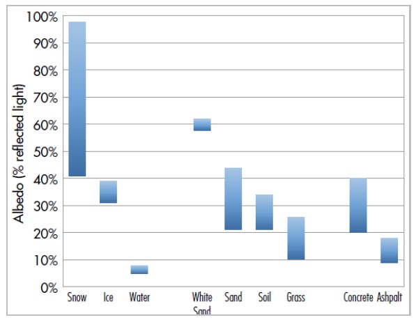
Albedo ranges for different surfaces
Naturally occurring lighter surfaces such as snow and ice return the highest albedo
values (up to about 90% in some cases) while soil and grass delivers a peak albedo of
about 35%. It is clear that by incorporating certain design changes to utilize albedo, a
considerable bifacial gain from the system is possible.
A good starting point is to ascertain the composition on solar radiation, i.e. the ratio
of direct to diffused radiation. Locations where conditions of high-diffused radiation
prevail are prime candidates for deployment of bifacial systems as the bifacial ratio of
the selected module ties in to the site conditions. Site latitude, proximity to
geographic features such as coastal regions etc. determine the diffused component of
radiation and ultimately the bifacial gain from the system.
While albedo for a location is predetermined by its location and site conditions, it is
possible to engineer conditions to enhance albedo and boost generation. One such
technique is selective coating the ground surface with white paint or a reflective
surface as shown in Figure 7.
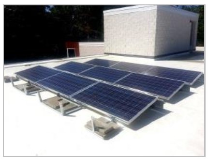
Figure 7: Selective coating of ground surface6
Selective coating is economically viable for rooftop or small plants without affecting
the CAPEX significantly. This is not practical for utility scale projects and hence
techniques that are more practical are employed, some of these are;
- MMS height
- MMS design
- Greater tilt
- Larger pitch
The purpose of raising the MMS height is to facilitate capture of additional diffused
albedo light at the rear surface. Increasing the height also results in less intense
shadows on the rear side of the module, thereby decreasing the impact of shading.
Electrical mismatch is maintained at a minimum as rear modules in a string are exposed
to more homogenous reflected radiation. Where MMS height for monofacial modules is
typically 1m, in bifacial systems a height between 1m of 2m is common. Increasing the
MMS height further results in diminishing returns. On the downside, increased MMS height
presents challenges during installation and O&M activity.
The same holds for trackers, where the use of bifacial modules has been shown to produce
significantly higher gains than bifacial modules installed on fixed tilt MMS. Evidence
of this is the high proportion of projects with bifacial modules currently in
development use trackers. Results presented by tracker manufacturer Soltech show the
influence of MMS height in Figure 8.
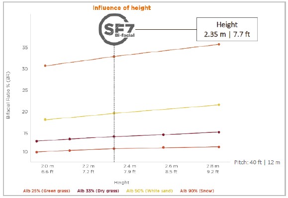
Figure 8: Influence of height on bifacial ratio7
It can be seen that influence of height beyond a certain limit results in diminishing
returns8. The data is presented for different surfaces (albedo).
MMS designs for bifacial application have changed on the rear side to reduce shading from
reflected light. As current in bifacial modules is higher, shading can result in
formation of hotspots (Figure 9), posing a fire hazard.
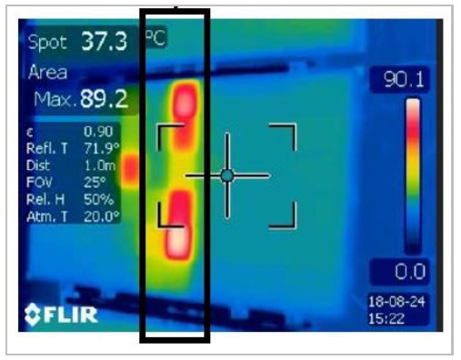
Figure 9: Shading from the torque tube resulting in hotspot9
For bifacial modules on fixed tilt MMS, higher tilt angles are implemented to increase
exposure of the rear side to diffused and reflected light. A caveat however is the
increased load and a structure susceptible to higher wind loading. Compensating for
these may affect project IRR. For systems at particularly high latitudes, inter row
shading concerns may arise if a sufficient pitch is not maintained. In tracking plants,
the gain can be expected to vary more significantly than a fixed tilt system.
Another effective mechanism to increase the reflective area and diffused light is by
increasing the pitch as shown in Figure 10. Ground Coverage Ratio (GCR) is defined as
the ratio of collector width to pitch. GCR and tilt are connected as an increase in tilt
will require an increase in pitch to avoid inter row shading and in the case of bifacial
systems, higher albedo for the system. Increase in pitch also proves accessibility for
O&M activity.
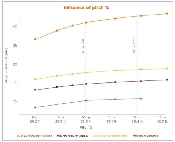
Figure 10: Effect of pitch on bifacial ratio10
Increasing the inter row spacing has a positive effect on the bifacial ratio which
delivers a higher energy output. Although the linear trend is proportion, beyond a
certain value, the graph tends to flatten out and the returns diminish. Beyond this
critical value, cabling, infrastructure and cost of additional land will add to CAPEX
thereby making the project less lucrative. The appropriate pitch for a site depends on
project location, MMS design and tilt in the case of fixed tilt system.
When bifacial modules are paired with trackers, the energy gains have been shown to be
significantly higher than a bifacial on fixed tilt installation. This is because
trackers have a greater impact on the albedo and GCR, two key parameters that impact
rear side generation as shown in simulated results presented in Figure 11.

Figure 11: Influence of albedo (left) and GCR (right) on the two sides of
bifacial modules11
From the discussion, to configuring an optimal bifacial PV plant, site conditions are
considered in conjunction with the methods listed above to arrive at an optimal solution
that fulfills commercial and technical benchmarks of the project.
CURRENT SHORTCOMINGS
At present, modules are being tested and certified to IEC - 61215 which is inadequate for
measuring rear side generation of bifacial modules. A new standard is being developed by
the International Electrotechnial Commission (IEC) which shall include procedures to
measure IV characteristics of bifacial devices in natural or simulated environments. The
hurdle lies in the measurement method and determining the nameplate rating.
Presently, the available simulation software’s possess limitations in simulation energy
yields of bifacial systems which is down to the infancy of the technology. The absence
of reliable fields data to validate models can result in high uncertainty in predicted
yields which makes for non-bankable results.
APPLICATION OF BIFACIAL SYSTEMS
Their unique design makes bifacial modules useful where the use of monofacial modules
would not justifiable. Some areas of the application for bifacial modules are;
- Primarily in large PV fields utilizing trackers for further enhancement in energy
yields.
- As railings - where they are installed vertically.
- For soundproofing in building integrated PV systems.
- In snow heavy locations – due to high albedo, bifacial gain would be significant.
Such systems can produce energy all year.
- On Carports – With the emergence of EV’s these can serve to power charging points
Download as PDF